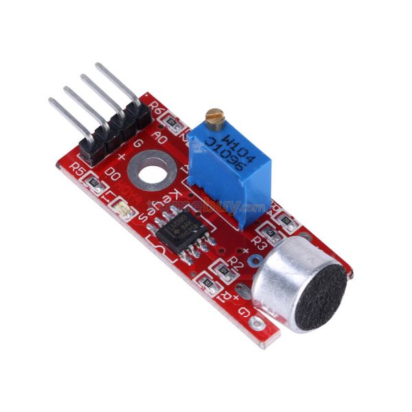
Audio Microphone Sound detection Sensor module MOD32 ,R14
$ 1.53
DescriptionTrue interactive hardware responds to its environment, and sound is one of the most natural triggers available. The KY-038 Sound Sensor Module provides your microcontroller with a simple, highly effective “ear.”Whether you are designing a classic clap-activated light switch for your bedroom, or an intelligent security node that triggers an alert when a window breaks, this module strips away the complexity of complex audio processing.Dual Output Modes (Analog vs. Digital)As seen in the product image, the board features a 4-pin header, giving you two completely different ways to read audio data:Analog Output (A0): This pin outputs a continuous, fluctuating voltage that directly mirrors the audio waveform picked up by the microphone. You can read this with your Arduino’s Analog-to-Digital Converter (ADC) to measure overall room volume or create sound-reactive visualizations.Digital Output (D0): This is a simple ON/OFF trigger. By adjusting the blue potentiometer (W104) with a small screwdriver, you set a specific volume threshold. When a sound (like a loud clap) crosses that threshold, the onboard LM393 chip instantly snaps the D0 pin HIGH or LOW. This allows you to trigger events using simple digitalRead() commands or hardware interrupts without writing heavy audio-sampling code.Important Expectation: Detection vs. RecognitionCrucial Design Note: This sensor is designed to detect the loudness or presence of sound. It is an envelope detector, not a high-fidelity recording microphone. It cannot recognize specific spoken words, identify voice commands, or record MP3 audio files. Its primary job is to act as an acoustic trigger.Visual CalibrationTo make prototyping completely seamless, the board includes two built-in SMD LEDs:Power LED: Illuminates continuously when the module receives 3.3V or 5V power.Trigger LED: Flashes on the exact moment the microphone detects a sound that exceeds your tuned digital threshold. This allows you to visually calibrate the sensitivity of your clap-switch before you even write a single line of code!Key Features:High Sensitivity: The electret condenser microphone capsule is highly responsive to sharp acoustic transients (claps, snaps, knocks).Hardware Filtering: The LM393 comparator handles threshold logic at the hardware level, freeing up your microcontroller’s processing power.Broad Compatibility: Operates flawlessly on both standard 5V logic (Arduino Uno) and 3.3V logic (ESP32, Raspberry Pi).Technical Specifications:Microphone Type: Electret CondenserComparator IC: LM393Operating Voltage: 3.3V to 5V DCOutputs: 1x Analog (Real-time voltage), 1x Digital (Threshold trigger)Mounting: Features a pre-drilled M3 screw hole for secure enclosure mountingDimensions: ~32mm x 17mm x 15mmIdeal Applications:Clap-activated or knock-activated electrical relaysSound-reactive LED light strips and matrix displaysSmart home security systems (detecting glass breaking or dog barking)Educational labs demonstrating analog-to-digital signal conversionGetting started with the Audio Microphone Sound detection moduleThis post shows how to use the microphone sound sensor with the Arduino board.In this example, a microphone sensor will detect the sound intensity of your surroundings and will light up an LED if the sound intensity is above a certain threshold.The microphone sound sensor, as the name says, detects sound. It gives a measurement of how loud a sound is.There are a wide variety of these sensors. In the figure below you can see the most common used with the Arduino.At the leftmost side, you can see the KY-038 and at the right the LM393 microphone sound sensor.Both sensor modules have a built-in potentiometer to adjust the sensitivity of the digital output pin.Wiring your sensor to the Arduino is pretty straight forward:PinWiring to ArduinoA0Analog pinsD0Digital pinsGNDGNDVCC5VIf you’re using the LM393 module, you should connect the OUT pin to an Arduino digital pin.Hardware requiredMicrophone sound sensorArduino UNOBreadboardLED 220 0hm resistor Jumper wires Connecting the HardwareCodeUpload the following code to your Arduino board.int ledPin=13; int sensorPin=7; boolean val =0;void setup(){ pinMode(ledPin, OUTPUT); pinMode(sensorPin, INPUT); Serial.begin (9600); }void loop (){ val =digitalRead(sensorPin); Serial.println (val); // when the sensor detects a signal above the threshold value, LED flashes if (val==HIGH) { digitalWrite(ledPin, HIGH); } else { digitalWrite(ledPin, LOW); } }After uploading the code, you can clap next to the sensor. If the LED is not lighting up, you need to change the sensor sensitivity by rotating the potentiometer. You can also adjust the sensitivity so that the LED follows the beat of a certain music.NOTE:That example outputs 1, if the sound levels are above a certain threshold, and 0, if they are below.If you are always getting 1, it means that your threshold is too low.You need to adjust the threshold of your sensor by rotating the potentiometer at the back. One LED indicates the sensor is being powered, and the other indicates the digital output. So, if you are always getting 1, the two LEDs on the sensor are lit. If you get 0, the second LED should be off. Alternatively, if your sensor has an analog output pin, you can read that pin instead using the analogRead() function. You’ll get varying values between 0 and 255 depending on the sound intensity.
Related products
-
Audio Microphone Sound detection Sensor module MOD32 ,R14Select options
This product has multiple variants. The options may be chosen on the product page
-
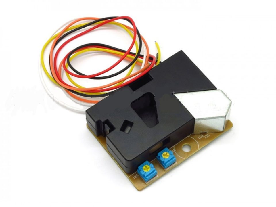 DSM501A Dust Sensor Module PM2.5 Detection Dector COM46, R28Select options
This product has multiple variants. The options may be chosen on the product page
DSM501A Dust Sensor Module PM2.5 Detection Dector COM46, R28Select options
This product has multiple variants. The options may be chosen on the product page
-
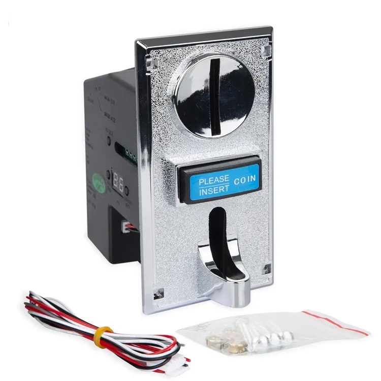 HX-916 Multi Coin Acceptor Programmable for Vending Machines (9 coins types) COM45, R37Select options
This product has multiple variants. The options may be chosen on the product page
HX-916 Multi Coin Acceptor Programmable for Vending Machines (9 coins types) COM45, R37Select options
This product has multiple variants. The options may be chosen on the product page